- All
- Product Name
- Product Keyword
- Product Model
- Product Summary
- Product Description
- Multi Field Search
Views: 0 Author: Site Editor Publish Time: 2026-09-22 Origin: Site
In heavy industrial, automotive, and aerospace applications, unprotected wiring exposed to extreme ambient or radiant heat faces rapid degradation. This leads to electrical shorts, system failures, and severe safety hazards. Engineers and procurement teams must specify thermal protection that survives continuous high-temperature exposure. The material must also withstand mechanical abrasion, chemical ingress, and spatial constraints without causing thermal bottlenecking. Understanding the exact thermal and mechanical mechanisms of a fiberglass insulation sleeve is necessary for specifying the correct coating, wall thickness, and weave density. Proper specification ensures long-term operational reliability, safety compliance, and optimal system performance. We will break down the exact specifications needed to protect high-temperature wires in harsh environments. You need to know how these materials behave on the shop floor and in the field to prevent catastrophic electrical failures.
Thermal Thresholds Dictate Material Choice: Standard fiberglass withstands continuous temperatures up to 1,000°F (537°C), but peak exposure, radiant heat, and molten splash require specific secondary coatings.
Coatings Define Application Suitability: Selecting between uncoated, silicone-coated, or aluminum-laminated sleeves depends entirely on whether the primary threat is ambient heat, radiant heat, or fluid contamination.
Dielectric and Mechanical Dual-Functionality: Beyond thermal protection, high-quality sleeving provides essential dielectric strength to prevent arcing, mechanical durability to resist vibration-induced chafing, and critical flame retardancy.
Customization Mitigates Installation Failure: Partnering with a specialized insulation sleeve manufacturer for custom diameters, wall thicknesses, and closure mechanisms prevents premature failure caused by improper fitment and routing constraints.
Texturized, braided, or knitted E-glass fiber traps dead air within its physical structure. This trapped air creates a highly effective thermal barrier. It significantly slows heat transfer from the external environment to the internal wire jacket. High-density weaves offer superior structural integrity. However, they conduct heat slightly faster than low-density, highly texturized knits. Low-density structures trap more air volume. This optimizes thermal resistance in purely ambient heat scenarios. The specific heat capacity of the glass fibers absorbs thermal energy. This delays the temperature rise of the internal components during sudden heat spikes. You must balance the need for thermal insulation with the physical durability required by the operating environment. In a foundry, a dense braid survives physical impacts better. In a static oven, a looser knit provides better insulation.
Fiberglass naturally acts as a reliable dielectric barrier. It prevents electrical arcing between adjacent cables or conductive chassis components. Voltage breakdown ratings depend heavily on weave tightness and overall wall thickness. Tighter braids leave fewer microscopic gaps. This enhances electrical isolation in high-voltage applications. Contaminants like dirt, oil, or moisture bridge these microscopic gaps. This reduces the dielectric effectiveness of bare fiberglass. In heavily contaminated environments, secondary coatings become necessary to maintain electrical safety. The inherent insulating properties of the glass fibers ensure that even if the primary wire jacket fails, the sleeve provides a secondary fail-safe against short circuits. We regularly see bare fiberglass sleeves save entire control panels from burning down when a primary wire jacket melts.
The robust fiberglass matrix absorbs physical impacts effectively. It resists chafing in high-vibration environments like engine bays and heavy machinery. The braided structure allows for significant radial expansion. This accommodates the thermal expansion and contraction of internal wires. It maintains structural integrity during extreme temperature shifts. Bare fiberglass provides baseline resistance to many industrial chemicals, solvents, and hydraulic fluids. The fibers do not degrade when exposed to most acids or alkalis. This chemical inertness ensures the sleeve remains structurally sound even in harsh processing facilities. The mechanical flexibility allows installers to route cables through tight bulkheads without compromising the protective barrier.
E-glass fibers are inherently non-combustible. They will not ignite, melt, or support a flame under normal atmospheric conditions. Specific weaves and specialized coatings help these sleeves achieve stringent VW-1 flame test ratings. This prevents fire propagation along long cable harnesses during catastrophic electrical faults. By starving the localized fire of oxygen and resisting ignition, the sleeve contains the damage. It prevents a localized short circuit from escalating into a full-system fire. The non-combustible nature of the base material means it does not release toxic smoke or halogen gases when exposed to direct flame. This is a major safety factor in enclosed spaces like aircraft cabins or transit vehicles.
A standard fiberglass cable sleeve provides excellent baseline protection. It fits best in dry environments requiring maximum flexibility. These sleeves handle continuous ambient heat up to 1,000°F (537°C). Manufacturers often heat-treat or anneal these sleeves to remove organic binders. This prevents smoke generation during initial heat-up. Uncoated sleeves are prone to fluid absorption. They act like a wick if exposed to oil or water. They fray if not cut or terminated correctly. Bare fiberglass lacks the ability to reflect radiant heat effectively. It relies entirely on its thickness and trapped air to insulate against thermal transfer. Use this variant for internal oven wiring, dry heating elements, and static high-temperature sensors.
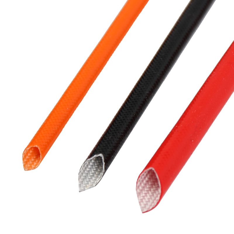
Heavy industrial settings require upgraded protection. Steel mills, foundries, and heavy transit systems expose wires to molten metal splash, welding sparks, and hydraulic fluid leaks. A silicone fiberglass sleeve excels in these brutal environments. The thick silicone rubber coating sheds molten splash immediately. The extreme temperature difference causes the molten material to bead and roll off before heat transfers to the core. It creates a waterproof, highly dielectric barrier. These are typically rated for 500°F (260°C) continuous exposure. They withstand short-term excursions up to 3,000°F (1650°C). Standard wall options maintain flexibility for complex routing. Heavy wall variants maximize splash and abrasion resistance in high-risk zones. In a steel mill, a slag hauler's hydraulic lines sit inches from molten material. A standard sleeve would burn through instantly. The heavy-wall silicone variant provides a 15-to-30-second window for the operator to shut down the equipment safely if a splash occurs.
Proximity to exhaust systems, furnaces, and engine manifolds introduces intense radiant heat. aluminum foil fiberglass sleeving is engineered specifically for these zones. The metallic surface reflects up to 90% of radiant heat away from the internal components. The fiberglass substrate provides the necessary insulation against any conductive heat that penetrates the foil. Performance relies heavily on the lamination integrity between the foil and the fiberglass. High-quality manufacturing prevents delamination during aggressive thermal cycling. If the adhesive layer fails, the foil peels away, completely destroying the radiant reflection capabilities. These sleeves fit static applications where radiant heat is the primary failure mode. Automotive engineers routing oxygen sensor wires near a catalytic converter face radiant temperatures exceeding 1,200°F. The aluminum layer bounces this infrared energy away, keeping the internal wire jacket well below its melting point.
Sleeve Type | Continuous Temp Limit | Peak Temp Limit | Primary Protection Mode | Best Application Environment |
|---|---|---|---|---|
Uncoated Fiberglass | 1,000°F (537°C) | 1,500°F (815°C) | Ambient heat insulation | Dry, static, high ambient heat |
Silicone Coated | 500°F (260°C) | 3,000°F (1650°C) | Molten splash & fluid barrier | Foundries, heavy machinery, wet zones |
Aluminum Foil Laminated | 400°F (204°C) | 3,000°F (1650°C) Radiant | Radiant heat reflection | Exhaust routing, furnace proximity |
Calculating the actual thermal load on the wire is the first necessary step. You must differentiate between continuous operating temperatures and short-term peak excursions. A sleeve rated for 3,000°F peak exposure will quickly fail if subjected to 1,000°F continuously. The silicone coating degrades and turns to ash under sustained excessive heat. Always match the continuous rating of the high temperature insulation sleeve to the baseline ambient environment. Reserve the peak ratings for temporary events like ladle pours, exhaust backfires, or momentary friction heat. Overestimating the continuous capability of a coated sleeve leads to premature embrittlement and catastrophic failure.
Assess the presence of aggressive fluids in the operating environment. Aviation applications involve Skydrol, a highly corrosive hydraulic fluid. Automotive environments expose wiring to engine oil, brake fluid, and road salts. UV exposure degrades certain synthetic materials over time. If fluid ingress is a known risk, an uncoated sleeve fails by wicking moisture directly to the wire jacket. Coated variants become strictly necessary in these environments. The silicone layer acts as an impermeable barrier. It protects both the fiberglass substrate and the internal wiring from chemical degradation and galvanic corrosion caused by trapped moisture.
Heavy silicone or aluminum coatings introduce specific bend radius limitations. Stiff sleeves kink when forced around tight corners. Kinking creates weak points in the thermal barrier and stresses the internal wires. Tubular slip-on sleeves work best for new assemblies where connectors are not yet installed. Wrap-around split sleeves allow for retrofitting existing systems. They eliminate the need to disconnect primary fluid lines or complex electrical harnesses. Split sleeves utilize high-temperature hook-and-loop fasteners or metallic snaps. This ensures a secure closure that maintains thermal integrity along the entire length of the routed cable.
Balancing the higher upfront cost of coated or custom sleeves against the reduction in maintenance downtime is necessary. Frequent replacement of cheap, under-specified sleeving causes massive operational delays. A properly specified sleeve lasts the entire lifecycle of the internal cable harness. Track the replacement frequency of your current thermal protection. If you replace sleeves every few months due to embrittlement or fluid degradation, you have the wrong material. Upgrading to a heavier wall thickness or a different coating extends maintenance intervals from months to years.
Improper cutting of uncoated fiberglass leads to airborne particulates. It compromises the structural integrity of the sleeve ends. Frayed ends allow moisture and dirt to penetrate the protective barrier. Mitigate this by utilizing hot knives or specialized heavy-duty shears. Hot cutting melts the synthetic binders slightly, sealing the edge. Alternatively, specify pre-cut lengths directly from the manufacturer. This ensures clean, sealed edges that will not unravel during installation or operation. Securing the terminated ends with high-temperature silicone tape or stainless steel tie wraps further prevents fraying and seals the assembly against contamination.
Measure the required length, adding a 5% margin for routing slack.
Wrap the cut zone tightly with masking tape to hold the fibers in place.
Use a heated cutting tool to slice directly through the center of the taped section.
Remove the tape carefully to avoid pulling loose fibers.
Immediately seal the end with high-temperature silicone tape or a mechanical clamp.
Using overly thick insulation on high-current cables creates a dangerous thermal bottleneck. Electrical conductors generate heat due to internal resistance. The sleeve traps this internally generated heat. This leads to internal wire failure despite robust external protection. Calculate the ampacity derating of the wire when enclosing it in a high-R-value sleeve. You may need to upsize the internal wire gauge to reduce internal heat generation. Balancing external heat rejection with internal heat dissipation is mandatory for high-power electrical harnesses. Over-insulating destroys cables just as fast as under-insulating.
Coated sleeves in environments with rapid temperature fluctuations trap condensation. Equipment that heats up and cools down daily passes through the dew point frequently. This trapped moisture leads to internal wire corrosion and degraded dielectric performance. Implement proper drainage points at the lowest routing elevations. Puncturing small weep holes at the bottom of a silicone sleeve loop allows condensation to escape. Utilize breathable, uncoated sleeves if external fluid ingress is not a primary threat. Allowing the assembly to breathe prevents the accumulation of corrosive moisture within the harness.
Failure Mode | Visual Indicator | Root Cause | Corrective Action |
|---|---|---|---|
Embrittlement | Silicone coating cracking or flaking off | Continuous temperature exceeded rating | Switch to uncoated fiberglass or silica sleeve |
Delamination | Aluminum foil peeling from substrate | Excessive physical abrasion or moisture | Reroute cable away from physical contact points |
Internal Melting | Wire jacket fused to inside of sleeve | Thermal bottlenecking (Joule heating) | Upsize internal wire gauge to reduce resistance |
Fraying Ends | Loose fiberglass strands at terminations | Improper cold cutting technique | Use hot knife and seal with silicone tape |
Ensure the selected sleeve meets all relevant regulatory requirements. Look for UL 1441 certification for electrical sleeving. Verify RoHS and REACH compliance to meet environmental and safety directives. Aerospace applications require specific SAE certifications for flammability and fluid resistance. Automotive environments demand strict adherence to ISO standards. Using non-compliant sleeving voids equipment warranties and leads to failed safety inspections. Always request documentation from the manufacturer to prove the materials meet the specific codes governing your industry sector.
Off-the-shelf products do not always fit complex assemblies. Scenarios requiring non-standard diameters or specific wall thicknesses demand a custom insulation sleeve. Standard sizes might leave too much air gap, causing the sleeve to snag on moving parts. Too tight of a fit makes installation impossible and restricts wire flexibility. Custom colors aid in phase identification for complex electrical panels. Specialized closure systems streamline installation on existing lines. Hook-and-loop fasteners, metal snaps, or high-temperature adhesives allow technicians to wrap cables without dismantling the entire system. Custom engineering ensures the protection matches the exact geometry of the application.
Evaluate your insulation sleeve manufacturer carefully. Look for ISO 9001 certification and strict batch testing protocols. A reliable partner provides comprehensive material data sheets. They supply independent dielectric testing reports to verify performance claims. Traceability is non-negotiable in aerospace, automotive, and heavy industrial sectors. The manufacturer must trace every spool of sleeving back to the original raw material batch. This ensures consistent thermal and mechanical performance across large production runs. It provides accountability in the event of a field failure.
Never commit to high-volume production runs without physical testing. Request sample lengths to verify physical fitment, flexibility, and thermal performance. Test the samples in the actual operating environment. A sleeve that performs well on a data sheet might fail due to unforeseen abrasion or chemical exposure in the field. Factor prototyping cycles into your project lead times to avoid costly rework. Work closely with the manufacturer's engineering team during this phase. Their experience identifies routing issues or material incompatibilities before they become expensive production bottlenecks.
Install the sample sleeve over the exact wire gauge used in the application.
Route the assembly through the tightest required bend radius to check for kinking.
Expose the assembly to the maximum expected ambient temperature for 48 hours.
Apply any relevant fluids to test barrier integrity.
Perform a dielectric withstand test to ensure no electrical leakage occurs after thermal and chemical exposure.
Audit your facility's thermal zones to map out exact continuous and peak temperature exposures for all critical wiring harnesses.
Measure the outer diameter of your existing cable bundles and add a 10% clearance margin to determine the required sleeve size.
Order physical samples of uncoated, silicone-coated, and aluminum-laminated sleeves to conduct on-site abrasion and fluid resistance tests.
Update your procurement specifications to include exact UL, RoHS, or SAE compliance requirements before issuing purchase orders.
A: Uncoated fiberglass sleeves withstand continuous ambient temperatures up to 1,000°F (537°C). Silicone-coated variants handle continuous temperatures around 500°F (260°C) but repel molten splash and peak excursions up to 3,000°F (1650°C) for short durations.
A: Yes. E-glass fibers possess inherent dielectric properties that prevent electrical arcing. Adding a silicone coating significantly increases the voltage breakdown resistance. This makes it highly effective for high-voltage applications in contaminated environments.
A: Fiberglass is inherently non-combustible and will not support a flame. Many coated variants are specifically engineered and tested to meet stringent UL VW-1 self-extinguishing ratings. This prevents fire propagation along cable harnesses.
A: The best practice is to use a hot knife. This slightly melts the synthetic binders to seal the edge. Alternatively, use specialized heavy-duty shears and secure the terminated ends with high-temperature tape or heat-shrink tubing.
A: Silicone-coated sleeves provide fluid resistance, shed molten metal splash, and offer higher dielectric strength. Standard uncoated fiberglass offers higher continuous ambient heat resistance but lacks protection against moisture, oils, and radiant heat.
A: Yes, but caution is required. Heavy physical abrasion or extreme moisture causes the foil to delaminate from the fiberglass substrate. It fits best in protected outdoor routing away from direct physical impact.
A: Measure the maximum outer diameter of the wire or cable bundle. Add a 10-15% clearance margin. This extra space allows for flexibility, accommodates thermal expansion, and makes the installation process significantly easier.